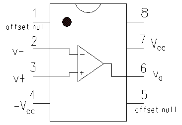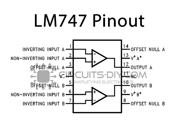

The analysis of the non inverting amplifier circuit is shown in figure 3. The input signal V i is connected directly to the non-inverting terminal and the input current is essentially zero (ideal op-amp), the input impedance (or Resistance) seen by the source is very large (ideally infinite).Ĭase-2: When op-amp has a finite open-loop gain, A OL (Practical case) Another conclusion can be drawn from the above equation is that the gain is always greater than unity. There are two input pins, pin 2 and pin 3. Pin 7 is connected to the positive voltage of the power supply. Pin 4 is either connected to ground or a negative voltage value from 3 to 18 volts.

The closed-loop voltage gain A v is given byįrom voltage gain A v, we can see that the output is in phase with the input. The power for the op-amp is provided through pins 4 and 7. The currents entering both terminals of the op-amp are zero since the op-amp is ideal. Since the op-amp is ideal and negative feedback is present, the voltage of the inverting terminal (V −) is equal to the voltage of the non-inverting terminal (V + = V i), according to the virtual short concept. The analysis of the non-inverting amplifier circuit is shown in figure 2.

1 Non-inverting amplifier AnalysisĬase-1: When op-amp is ideal i.e. The input signal V i is applied directly to the non-inverting terminal while one side of resistor R 1 is connected to the inverting terminal and the other side is at the ground. Figure 1 shows the basic non-inverting operational amplifier.


 0 kommentar(er)
